It was time for us to test out the designs for our PCB that would take care of the motor control.
In a true hackerspace fashion instead of ordering the PCB we decided to built the capacity to produce our own (much needed moving forward). We could not settle for a simple single-side capability with no solder mask, so we shot for a typical side-project extravaganza 🙂 What we ended up with was a double side capable UV exposer controlled for timing and after many tests the expertise to apply solder mask for uber cool finishing for our diy PCBs.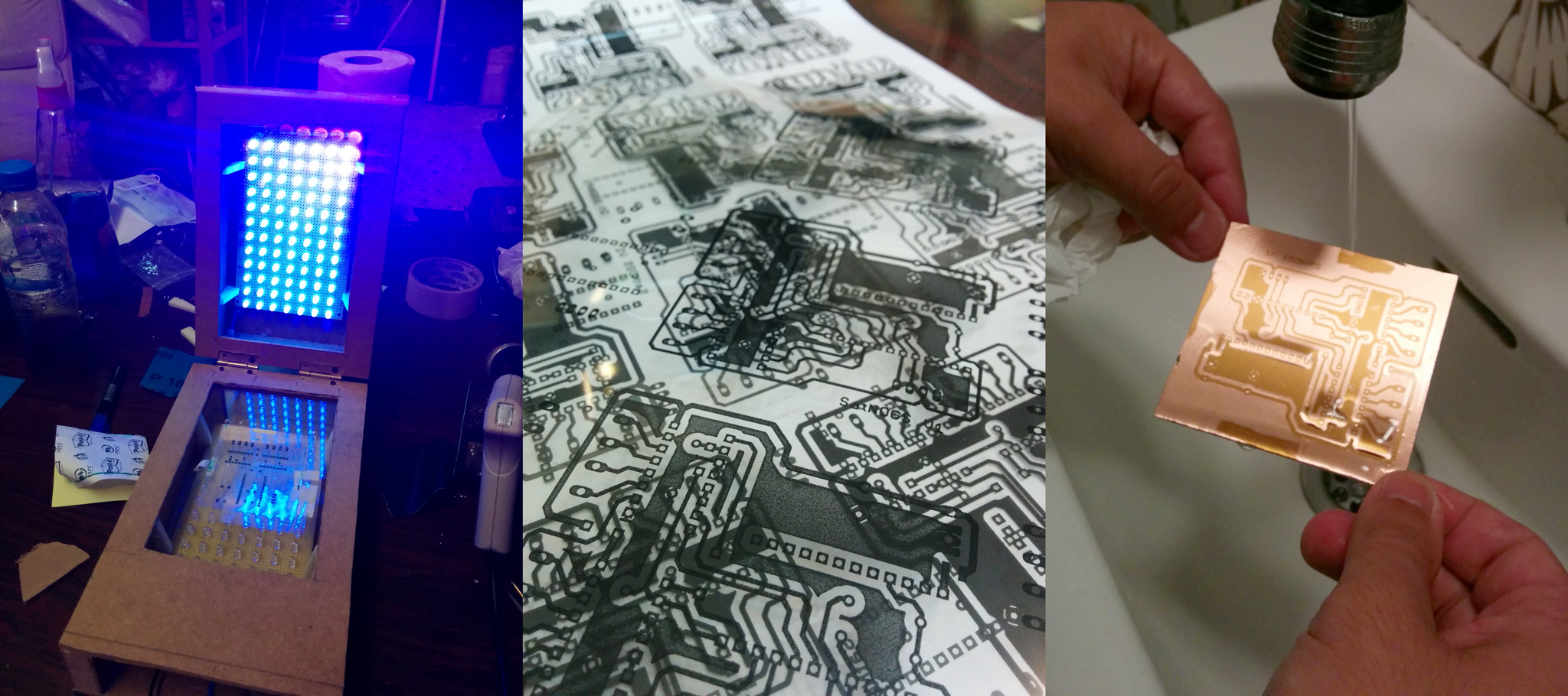
Back to SatNOGS specific PCBs the design was slightly changed from v1. We changed the capacitor, rerouted for optimal setup the board and thanks to [n0p] comments we added breakouts for unused Arduino pins (you never know what you will need!).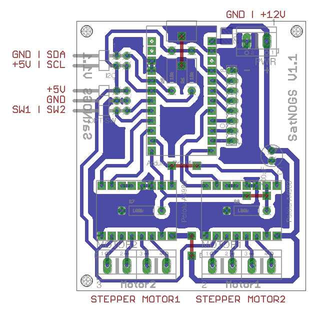
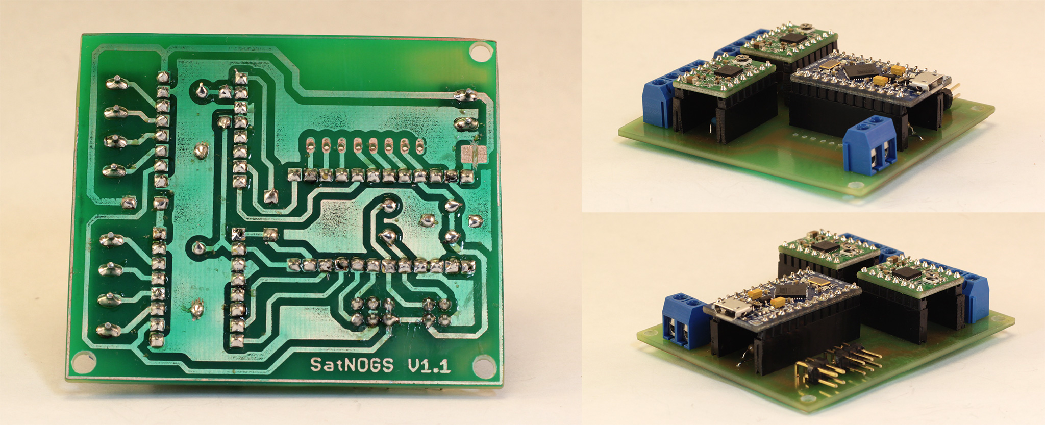
Production went smoothly and the PCB test showed that everything was in place correctly!
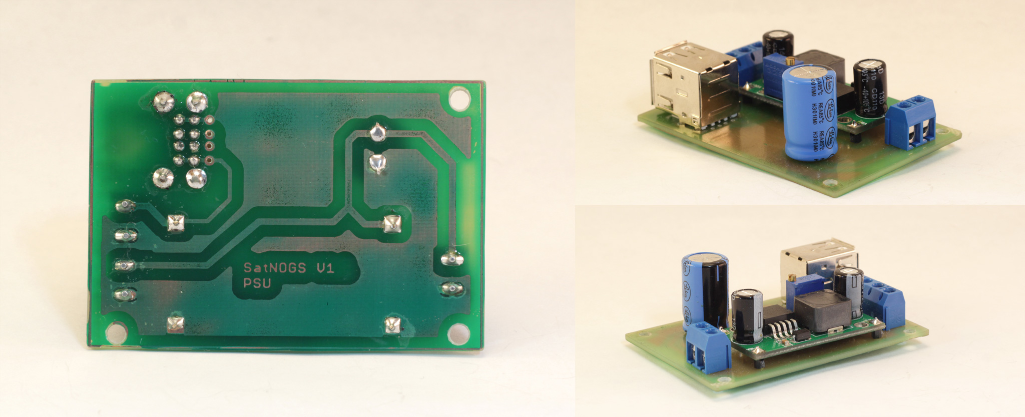
Having the finished v1.1 motor control PCB ready we thought that we could tidy up our power circuits too. That called for a PSU PCB tailored to our needs. Agis, our team electronics expert, quickly designed a PSU PCB based around a Voltage Regulator capable of having an input of 12V DC and an output of again 12V DC plus 5V DC stable through USB Type A too.
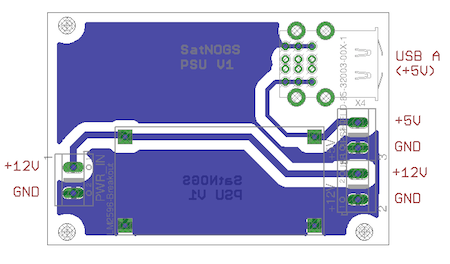 Production once again was smooth and we ended up with our PSU PCB. Pics below are from a slightly modified version with a cap (both designs can be found in our repo).
Detailed designs and Gerber files can be found in our Github repo
Next steps for our electronics will be to focus on the auto-homing circuits (using the handy breakouts!). A separate log on that will follow!


